|
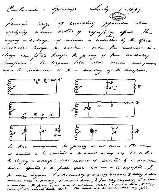
Colorado Springs
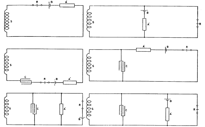
In these arrangements the primary is not shown. The same is assumed to be connected in the circuit in any way but so that the charging or discharging of the condenser is controlled by a sensitive device affected by the feeble effects which are to be magnified. In the above diagrams 5 is the secondary of oscillatory transformer, B battery to strain sensitive device in secondary; A' sensitive device, R fine relay (magnetic); C condenser in secondary.
The
primary circuit which is not shown includes: a sensitive device,
battery, condenser and make-and-break device. This method with two
sensitive devices is very good.
This applies to a simple case, as the one here illustrated which was
one of the earliest arrangements.
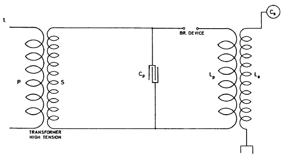
To prolong oscillation in primary and increase economy one of the schemes before considered may be resorted to. One of these is illustrated in Fig. 2. which follows: in this arrangement the currents through the break device are much smaller and the oscillations started by the operation of break in circuit LpCp continue much longer.
From this relation it is evident that, other difficulties or disadvantages not considering the arrangement as illustrated in Fig. 2. should be superior to that in Fig. 1. It secures two chief advantages: 1) less current through the break and more through the primary and 2) longer and better oscillation in circuit including primary because it is easy to constitute such a system without break with an extremely small resistance or frictional waste.
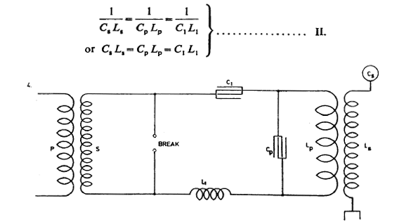
Fig. 3. illustrates an arrangement similar to that shown in Fig. 2. but with a condenser in each branch. The same considerations made in regard to Fig. 2. hold good for this and in both cases, if there is to be resonance and best conditions attained, the circuit including the break should have the same period and be in phase with primary circuit LpCp and secondary LSCS.
Referring to Fig. 2. as the simpler, this is the case when the relation between C1 and self-induction in this circuit is such that they annul each other at that frequency. Fig. 4 — a further modification shows the system with inductance Lx in circuit. To satisfy above conditions we must have
Rx being the resistance including the arc. Since in most cases, even with the arc included, /?, will be negligible against pL1 we have again
From all the above considerations we get a general relation between the constants of all the three circuits which is expressed by:
We have seen from the preceding that of the quantities considered p
was given by arbitrary selection of the wave length, Ls necessarily
by the wire and design of secondary and, lastly, Cs as following
from the two preceding quantities. One more quantity is, however,
given by practical considerations and that is C1. Namely, this
capacity C1, must be sufficient to take up the entire energy of the
transformer, if all things are rightly proportioned. Now let P' be
the e.m.f. on the secondary of the supply transformer, then there
will be stored each time in condenser C1 a quantity of energy
M is here the total power of the transformer expended and expressed
in watts, P' the pressure of secondary (average as defined) and p1
as before stated the frequency of the break. The quantity C1
thus being given in each case, these remain still to be determined:
Lp, L1 and Cp.
Presently then all the quantities are known for determining the constants of circuit Lp Cp from two equations
From this T=4.836 1/105 as calculated. This gives n=1/T=20,700 per sec. approx. With this vibration λ was nearly 9 miles or λ/4=2.25 miles. Actually, there was only one mile of secondary wire but owing to the large capacity (distributed) in the secondary the vibration was much slower than should be inferred from the length of wire. We may estimate the ideal capacity, which associated with the inductance of the secondary would give a vibration of the above frequency. Since there was resonance we have:
Last night the 50,000 volts transformer brought from New York broke
down. This happened upon connecting to the lower end of the
secondary a condenser composed of two adjustable brass plates of 20"
diam., one being connected to the ground, the other to the
secondary. The plates were about 5" apart. The experiment was
repeated with the transformer after repairing it and all was found
in good order.
This would give roughly the capacity
This would give
and n= 11,800 roughly. To this the primary to be adjusted for first approximate trials. Now the primary has six turns. Since one turn is approx. 7x 104 cm. we may put:
From this a rough idea of the capacity in primary may be gained. We get Cp=0.0717mfd. roughly. Taking capacity of one jar=0.003 mfd. we would want total 0.0717/0.003=24 jars approx. or 48 jars on each side of primary. This vibration would be impracticable under the present conditions as the transformer could not charge this number of jars. Although for stationary waves in ground it would be desirable to use such a low frequency the vibration will have to be quickened. An octave would require only 12 jars on each side.
This was tried and results were good although the
octave vibration had only 1 /4 of the energy as the fundamental
would have had. To get the true vibration we shall want
at least 8 turns in the primary with present transformer to keep the
capacity in the primary
within the limits given by the output of transformer. This would
then give 48 x 36/64 = 27 jars on each side. While this might do, still for best conditions
not more than 16 jars should be used on each side of primary. This
just taxes the transformer to full capacity within safe limits.
They also appeared frequently thicker on the bottom than on top. Can this be so? Perhaps it was only due to the fact that the portion close to the ground was nearer to the observer. The storm began to be perceptible at a distance as it grew dark and continuously increased. An instrument (rotating "coherer") was connected to ground and a plate above ground, as in my plan of telegraphy, and a condenser was used to magnify the effects transmitted through the ground.
This method of magnifying secures much better results and will be described in detail in many modifications. I used it in investigating properties of Lenard and Roentgen rays with excellent results. The relay was not adjusted very sensitively but it began to play, nevertheless, when the storm was still at a distance of about 80—100 miles, that is judging the distance from the velocity of sound. As the storm got nearer the adjustment had to be rendered less and less sensitive until the limit of the strength of the spring was reached, but even then it played at every discharge.
An ordinary bell was connected to earth and elevated terminal and often it also responded. A small spark gap was bridged by a bright spark when the lightning occurred in the neighbourhood. By holding the hands across the gap a shock was felt indicating the strength of the current passing between the ground and the insulated plate. As the storm receded the most interesting and valuable observation was made. It happened this way: the instrument was again adjusted so as to be more sensitive and to respond readily to every discharge which was seen or heard. It did so for a while, when it stopped. It was thought that the lightning was now too far and it may have been about SO miles away.
All of a sudden the instrument began again to play, continuously increasing in strength, although the storm was moving away rapidly. After some time, the indications again ceased but half an hour later the instrument began to record again. When it once more ceased the adjustment was rendered more delicate, in fact very considerably so, still the instrument failed to respond, but half an hour or so it again began to play and now the spring was tightened on the relay very much and still it indicated the discharges.
By this time the
storm had moved away far out of sight. By readjusting the instrument
and setting it again so as to be very sensitive, after some time
it again began to play periodically. The storm was now at a distance
greater than 200 miles at least. Later in the evening repeatedly the
instrument played and ceased, to play in intervals nearly of half an
hour although most of the horizon was clear by that time.
On the base it was about 51 feet and the sides were inclined at an angle of 45°. The sides were formed of light lattice work notched for the reception of the wires. The first turn of the secondary began some distance from the ground so that the average turn was smaller than it ought to have been, judging from dimensions, that is nearly 145 feet.
Nevertheless more wire was actually coiled up owing to the fact that there was some loss in the corners, and the wire not being perfectly straight added still further to the length so that 6 coils of wire were rolled up, their lengths being: 1000+1000+1005+1002+ +762+546=5315 feet total, No. 10 B. & S. wire. Deducting ends left gave very nearly 5280 feet or a mile =1610 meters approx. The wire was wound on by the help of a stand rolled on the floor and supporting the reel. The resistance of the wire was 5.55 ohms.
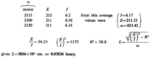
The readings were as follows:
With 40 turns placed at same distance we may take approximate
inductance to be about 42x 106 cm. Note: It was before assumed 5x
107 but the turns were a trifle closer.
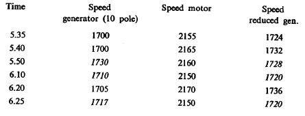
Speed of generator on station was taken by Mr. L. and on motor in exp. station by myself. The readings on generator were more liable to be underestimated. General results show that high values obtained on generator agree well with values obtained on motor. The latter can go a little faster without load. This 1 have observed with such motors before.
The reason for this may be found in the fact that the generator fluctuates about a certain average value, a greater momentum is impacted to the motor when the speed of the generator is above than when below that value. This will result in the motor making a few more revolutions than would strictly follow from the average value.
Or, the counter-electromotive force is out of phase
giving higher e.m.f. on motor then on generator, thus changing
amount of positive or negative slip. Taking average from three
evidently best readings we get on generator 1719, on motor 1722
which agrees fairly. Accordingly, with this generator ω will be
generally 2n X 29x5=911 or, for ordinary estimates ω =900.
From older notes: Consider generation of hydrogen for balloons in the ordinary way:
From this:
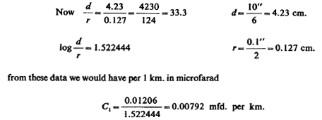
This gives C in microfarad per 1 km., according to the authority. Here the length of wire total is 5280 feet roughly or 5280 X 12x2.54=-160,934 cm. Taken as a pair of conductors this would give length 160,934/2=80,467 cm.
Now the length of the pair of parallel wires as supposed would be 80,467 cm. or 0.80467 km. or for the secondary the capacity would be C=0.80467xC1x2, double since both sides must be counted,
or
C=0.00792x2x0.80467=0.01584x0.80467= =0.012746 mfd. or 9x
105x0.012746=1274.6x9=11,471.4 cm. Evidently this is not applicable,
the capacity could be at the utmost 3000—4000 cm. judging from the
vibration of the secondary.
As has been already stated this result may be reached in two ways radically different — either by a high ratio of transformation or by resonant rise. For power transmission it seems that ultimately the former method must prevail, but where a small amount of energy is needed the latter method is unquestionably the better and simpler of the two. By placing the secondary in a very close inductive relation to the primary, the self-induction is diminished so that the self-induction in a highly economical machine of this kind would not seem to be an impediment in the way of obtaining a very high frequency, at least not one which could not be more or less overcome by scientific design of the machine.
But the distributed capacity is a troublesome element in such a machine and all the more so as the e.m.f. increases. When the pressure reaches a few million volts almost all the energy is taken in charging the condenser or capacity distributed along the wire. The difficulty becomes greater still when it is realized that in an economical machine the turns must be close together, which increases the drawbacks resulting from the distributed-capacity.
Now one way of reducing the internal capacity is to place between the turns, and in series with them, condensers of proper capacity, but this is not always practicable. This will be later considered more in detail. By such means the full rise of pressure on the terminal or terminals of the secondary may be obtained, which is impossible with distributed capacity of any magnitude. Very often only a small rise at the terminals can be obtained as all the charge remains "inside".
Now as to obtaining the required pressure by a resonant rise there are again two ways: either to place a secondary in loose connection to a primary thereby enabling the free vibration of the secondary to assert itself, or using a secondary in intimate connection with the primary and then raising the pressure by an additional coil — extra coil — or inductance not in inductive relation to the primary. The latter method I have found preferable when a very high e.m.f. is desired.
More particularly for purposes of telegraphy to any point of the globe which is one of the objects, I conclude that:
Experiences up to present
indicate flat spiral form of coil in sections as best suitable.
From this follows
With 40,000 volts we would be able to take 36/16x23=nearly 52 jars total or 104 on each side. Assuming 60,000 volts and say 48 of new jars on each side this would give capacity in the primary most suitable to the transformer 24x0.0025=0.06 mfd. and the inductance of the primary being say 7 x 104 cm. The period T would be
This is the case particularly when the oscillator is designed to take up the entire output of the generator, as may be in the present instance. But generally, when the oscillator is on a supply circuit distributing light and power the choice of capacity is unrestricted by such considerations. In most cases the advantages secured by using a very high frequency are so pronounced that the primary circuit will have to be designed with this feature in view.
The resistance of the primary circuit should be in any event as small as it is practicable to make it. I also think that generally, the inductance should be as small as practicable for that frequency which is supposed to be arbitrarily selected beforehand. When, however, the break number is comparatively small, that is, much smaller than the number of free vibrations, it is of great advantage to have the inductance great in order to give a greater momentum to the circuit and to thus enable it to vibrate longer after each break.
But if the break number is of a frequency comparable with that of the free vibrations, the inductance should be as small as possible for however small it be, the circuit will generally vibrate long enough. One more reason why the inductance should not be large in such a case is that, in the primary, it is unnecessary to raise the pressure by making pL/R very large.
Necessarily this factor
R will be large in a well designed circuit, but should be so chiefly
owing to an extremely small resistance and not owing to a high
self-induction. By making the inductance smaller a greater capacity
may be used and this will give a greater output, a feature which is
sometimes of importance. Of course, as the capacity becomes large
the difficulties in the make and break device increase, but with a
properly designed mercury break these difficulties are in large
measure overcome. I conclude from the above facts that the best way
to construct a primary in such a machine is to use thin sheet of
copper or at any rate a stranded
The actual length of the primary conductor, relative to that length which is obtained by dividing the velocity of light by 2n, n being the number of vibrations of the primary per second — is of little importance since the primary is generally but a very small fraction of that length, but I believe to have observed that it is preferable, in a slight degree, to make the conductor of such a length that, if l be this length and n the frequency, 2 Knl should = v, the velocity of light, and K should be a whole number and not a fraction.
At least this seems to hold good in circuits made very long expressly for the purpose of ascertaining whether there is truth in this idea which was arrived at by considering the ideal conditions of such a vibrating circuit. In this abstract case / should be rigorously equal to that half wave length which is obtained by computation from the velocity of light.
In practice it is invariably observed that
l is smaller and K is not as it should be = 1 but is often large
number, this simply following from the fact that the velocity of
propagation in a circuit with considerable inductance and capacity
is generally much smaller than that of light and often considerably
smaller. It is to be stated that for a number of reasons it is of
advantage, whatever be the actual length of the primary conductor,
to arrange it so that it is symmetrical with respect to the
condenser and the make-and-break device, one of the chief objects
being to secure the maximum difference of potential on the terminals
of the condenser. This consideration leads to the adoption of at
least two condensers in series, the primary generally joining the
outer coatings while the inner ones are bridged by the break device.
The secondary will have to be placed in the closest possible inductive relation to the primary and this will give an economical machine and one of relatively high frequency, since the inductances of the circuits by mutual reaction will be considerably reduced. But it is at once seen, that in a machine as here chiefly considered for the purposes followed from the outset, the connection between the primary and secondary can never be as close as in ordinary transformers, and the connection must be all the less intimate as the pressure on the secondary is increased since the wires must necessarily be placed at a greater distance from each other.
From this it follows that in such a machine the free vibration of the secondary can never be quite ignored even if the electromotive force is not extraordinarily high. Now directly as the free vibration of the secondary becomes an important element to consider in the design, the careful adjustment becomes obviously imperative. It goes without saying that pL/R should be as large as possible in all cases where resonant rise is one of the objects.
But here is where we find in practice, and particularly in a large machine, difficulties not easily overcome. Both the inductance and capacity grow rapidly as turns are added, so much so that very soon it is found the secondary period becomes together that of the primary. The chief drawback is, as has been already pointed out, the distributed capacity but also the inductance though in a lesser degree.
While the inductance in a certain sence has a great redeeming feature and is necessary, yet it stands in the way of obtaining a very high frequency in a large machine. To get a high electromotive force we must have many turns or turns of great length and this means great inductance and this again entails the drawbacks of slow vibration. Thus, in a large machine we encounter those difficulties which meet us in the design of too large a bridge, for instance, difficulties which are based on the very properties of matter and seemingly insuperable.
Make a wire rope of twice the section and it will not be able to carry a longer piece of its own, since the weight is increased in the same proportion as the section and the strain per unit of the latter remains the same. Fortunately for us in electrical machinery, of this kind at least, this limit is immensely remote owing to the wonderful properties of this agent
Still the difficulties encountered on account of the capacity and inductance, and usually on account of the insulation are such as will require great deal of persistent effort to be effectively done away with in these oscillators, if the results aimed at are to be achieved in a thoroughly practical manner. Much attention will be devoted to this part of the problem in perfecting the machines which are necessary for the successful carrying out of the projects of transmitting power as well as effecting communication with any point irrespective of distance.
But the machines for these two purposes will necessarily differ in design, since in one case — the first — a great amount of energy is imperative, while in the other only a high electromotive force and immense rate of momentary energy delivery is required.
The two most promising lines of development are
evidently these two: either to obtain the necessary electromotive
force in a secondary alone, or in an extra inductance, not
affected inductively by the primary or even by the secondary but
merely excited by the latter, the rise of pressure being due to a
great magnifying factor. The latter method has been found to be by
far the best when a high e.m.f. but not a great amount of energy is
required and there is scarcely any limit to the maximun pressure so
producible. But it does not seem to me as though this
method should be applied in power transmission contemplated, but
this will be decided in the future.
Theoretically it is possible to
entirely do away with the effect of distributed capacity in this
manner and to use an excessively large inductance and consequently
a large magnifying factor as well as magnifying transformation
ratio. The wave length in such a theoretical case will be then
exactly that which follows from the velocity of propagation of light.
This to follow up.
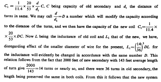
The diameter of this wire was only 1/11.4 of that of wire or cord No. 10 hence the capacity of the new secondary, assuming all other things to remain the same, would be only 1/11.4 of the capacity of the old secondary. The capacity of the new coil would be, however, reduced or increased in proportion to the length of the new wire relatively to the old and would be furthermore regulated by the distance of the turns.
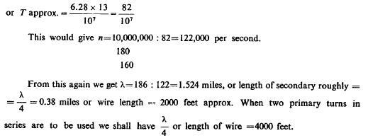
It was resolved to adopt 122,000 per second (see note before) in the primary as compared with 21,000 per second with the old secondary which was obtained with 15 jars on each side of the primary. For this vibration (122,000) the length of the new secondary should be about 2000 feet, this being the length of a quarter wave. Calling now the distance between the turns of the new coil d, its capacity as compared with that of old secondary of a length of 5280 feet would be:
It was of interest to determine the period of the combined primary and secondary system of the experimental oscillator and the following method was adopted. A coil wound with thin wire, turns separated by a string to reduce distributed capacity, was placed at a distance of a few feet from the vibrating system and so that it was about equally affected by the primary and secondary. One end of the coil was connected to earth and the other end was left free.
An idea was already obtained beforehand as to the frequency which was likely to be found but more wire was wound on the coil to enable the adjustment to be effected by taking off turns. Turns were then taken from the lower end of the coil until a maximum of spark length from free terminal was obtained. The coil then gave a spark 5" long. This took place when there were 1140 feet of wire on the coil, this length being found by measurement of resistance
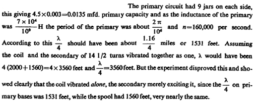
Neglecting the capacity of the coil this length should be =λ/4 or the quarter of a wave length. Of course, it was less but it was surmised that it would not be very much less. The total length of wave was then λ=4560 feet. From this would follow
Now the capacity in the primary circuit was ten new jars on each side, this making a five jars total or 5x0.0025=0.0125 mfd. or 125/104 mfd. From this the period of the system ought to have been
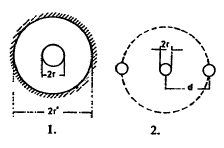
Here S is the surface of inner copper conductor, r' radius of inside hole of conductor outside of cable, r radius of copper conductor inside (Diag. 1.). Assuming now a cable wound up having n turns at a distance d, each turn may be considered as having a conductor on either side at distance d.
If we draw a circle of radius d around the conductor and imagine the inner surface conducting, we have the capacity of such a system according to above formula. Now in the case of a coil of this ideal surface we utilize only a small part which is approximately, when d is very large compared to
Now if there are n turns there will be (n—1) such systems as illustrated in Diagram 2. Taking air as insulation and neglecting the effect of the small thickness of other dielectric, we would then have the total capacity:
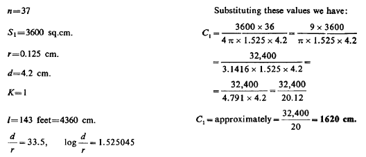
being the length of one turn. The values calculated out in this particular case of a secondary of 37 turns (36 1/2+connecting wires=approx. 37 turns) are as follows:
This is not far from the value found. It shows that an approximate
estimate may be made in this manner.
Here P is the potential, n the number of vibrations per 9xl0 ux2 second. In our case n may be 20,000 and then we may put
This shows that by only charging the
internal capacity to the insignificant pressure of 5800 volts we
would have to expend 1 H.P. Of course, normally the power is small
although the capacity is charged up to a much higher potential, but
the consideration shows why with a large distributed capacity a very
high pressure can not be obtained- on the free terminal. All the
electrical movement set up in the coil is taken up to fill the
condenser and little appears on the free end. This drawback
increases, of course, with the frequency and still more with the e.m.f.
The capacity in the primary was now reduced until to all evidence resonance was obtained, but the results were much inferior to what might have been expected, probably because pL/R was small owing to large resistance. One of the reasons was, however, that the capacity in the primary was too small to allow a considerable amount of energy to be transmitted upon the secondary.
To better the conditions, one of the balls of 30" diam. was
connected to the free terminal; this allowed a greater number of
jars in the primary to be used but the capacity of 38.1 cm. was by
far too small to secure the best condition of working. The
resonating condition in secondary was secured with approximately 7
jars on each side of the primary and when the ball was connected
with about 14 jars.
From this n= 195,000 per second. This vibration was far above that of the primary circuit working under favorable conditions, that is with the full number of jars. As the thin secondary did not yield any satisfactory results a coil was now associated with it. It was one used in some experiments before, having 260 turns of cord No. 10 (okonite) wound on a drum 2 feet in diam. and 6 feet long.
The total length of wire was 1560 feet and the capacity of the coil (as above) 1530 cm. This coil was connected to the free terminal of the secondary and the free end of the coil was placed vertically on the top of the same and in the prolongation of its axis. Fairly good resonant rise was obtained on the free end, the streamers being 2 1/2—3 feet long.
For best results secondary should have been tuned
to the same period as that of the coil. Conclusion of experiments
with thin wires was: results must be inferior as free vibration is
important.
The wave length will be:
before, wound on the secondary frame and placed at twice the
distance, the distributed
capacity will be not far from 1/2 x 1/10 or 1/20 of that of the old
secondary. The inductance of the new coil — neglecting effect of small diameter of No.
30 wire — will be one half of the old, hence the new system will
vibrate
We
should now, for the best suitable conditions, make the new system
vibrate only about 1/3 that number since this would be approximately
the vibration of the primary system, as above stated. Now taking the
capacity of the old secondary 1200 cm., that of the new would be
only 1200/20=60 cm.; we would have, therefore, to bring the pitch
down to make the capacity 9 times as large or 9x60=540 cm. or we
would have to put about 480 cm. on the free terminal of the new
coil.
To get a rough idea of how the coil might work suppose that on the primary there would be 40,000 volts and that there were 36 turns of secondary, then there would be theoretically an e.m.f. on the terminals of secondary 40,000x36=1,440,000 volts and, deducting with reference to mutual inductance 40%, we would have 1,444,000x0.6= 864,000 volts impressed or induced e.m.f.
Suppose now we had a capacity of 480 cm. on the free terminal as before estimated, the charge stored in this condenser would be:
The loss in this case, in spite of the great amount of
energy transformed, would be ridiculously small owing to the great e.m.f. despite comparatively high resistance of the secondary. But
this only seems so, for 544 ohms would be extremely small resistance
for such e.m.f. The theoretical case above considered is hardly
realizable, it would require an immense amount of energy.
This is a much smaller value than would be expected from previous approximate estimates. The correctness of the value found depends, among other things, chiefly on the correct determination of the period, for resonance might have been also obtained with a lower or upper harmonic, but this is not very likely to be the case as the vibration was very intense. There were approximately 5000 volts on primary turn.
Resistance of coil was
|


 and if
this value


 for one pair
of wires; there being 260 pairs, total capacity would be according
to this
  = 1532cm. =C1 (for coil). Now, the capacity in the
secondary was previously found 1080 cm. Hence the total capacity of
the system would be 1080+1532=2612 cm.=C. This, of course, gives
only an idea and the determination in this manner is far from being
exact Consider what the period would be with the capacity and
secondary and coil together as a whole. Since the coil will have
only about 12,000,000 cm. the inductance of the secondary will be
the chief governing factor. Taking this at 5x 107 cm. we would have
a total inductance 5x107x12x106 or (50+12)x 106 = 62 x 106 cm.




 28 units of weight total we get 4 unity of weight
hydrogen, much more than possible in former method. In case therefore a very
small weight is essentially required this method is most excellent.
Now as to electrolytic generation: 1 amp.-hour gives 37.3 milligram of hydrogen, 1000 amp.-hours
 lbs., 0.00561 lbs per cu. foot
gives
1.2 cu. feet per 1000 amp.-hours! Ridiculously small!
 farad or in centimeters we would have the capacity of condenser which the transformer will be
able to charge without considering resonant conditions or other
causes which may enable the transformer to charge many more jars
 cm. total. Now taking the
capacity of one jar as 0.003 mfd. or 2700 cm. this would give only
62,500/2,700 =
625/27=23 jars total, or in two series 46 jars on each side of primary. The
capacity of new jars will be probably 0.0025 and a correspondingly
greater number may be taken.
  per second.

 henry, the period of the system to be adopted for new
experimental








 times quicker than the old secondary
system. Since the old system vibrated 21,000 per sec. the new will
vibrate
6.3 times that or 132,000 times per second, this number being —n.
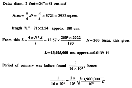
 as above. From above equation we find
