|
Colorado Springs
This,
however, is not always true. When the apparatus delivers a notable
amount of energy the curvature of the end of wire or terminal
attached to it should be such that the streamer breaks out only when
the pressure at the terminal is near the maximum. Otherwise, very
The greater the curvature of the terminal the smaller an electromotive force is required to enable the discharge to break out into the air. In fact, the curvature or the terminal may serve as an indication of the value of the e.m.f the apparatus is developing and it is often convenient to determine the e.m.f. approximately by observing how large a sphere will just prevent the streamers from breaking out, and for such purposes I have found it useful to provide the laboratory with such metallic spheres of different sizes up to 30" diam. It is of course necessary to guard in such experiments against errors which might be caused by any modification of the constants of the vibrating circuit through the addition to the system of a body of some capacity.
The latter should be such as to insure the maximum rise of the pressure. With apparatus of inadequate power the pressure may be very much diminished by the addition of capacity merely because there is not enough energy available to charge the same to the full pressure. It is a notable observation that these "extra coils" with one of the terminals free, enable the obtainment of practically any e.m.f. the limits being so far remote, that I would not hesitate in undertaking to produce sparks of thousands of feet in length in this manner.
Owing to this feature I expect that this method of raising the e.m.f. with an open coil will be recognized later as a material and beautiful advance in the art. No such pressures — even in the remotest degree, can be obtained with resonating circuits otherwise constituted with two terminals forming a closed path. It is also a fact that the highest pressure, at a free terminal, is obtained in that form of such apparatus in which one of the terminals is connected to the ground. But such "extra coils" with one terminal free may also be used with ordinary transformers and by using one such coil on each of the terminals of the transformer, practically any spark length may be reached.
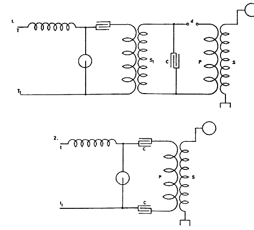
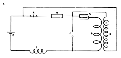
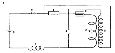
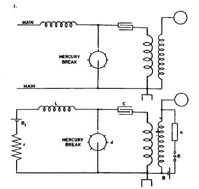
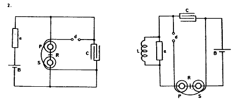
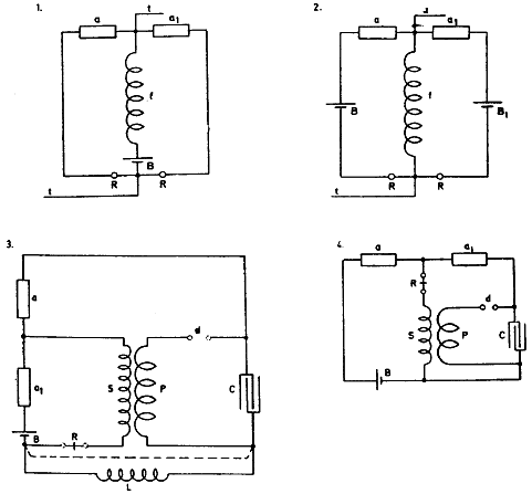
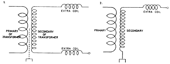
Of course, it is desirable that the frequency of the currents should be high, as with the common frequencies of supply circuits the lengths of the wires in the coils become too great. In the diagrams below the two typical arrangements with such an "extra coil" or coils are illustrated in which Diagram 1. illustrates their use with an ordinary transformer, which may have an iron core or not, and Diagram 2. shows typically the connection as I use it in my "single terminal" induction coil.
As has been stated on a previous
occasion in connection with this subject, to enable a considerable
rise of pressure to take place in a circuit, the same must be
tolerably free from inductive influences of other circuits. It
follows from this that, although with a secondary in loose
connection with a primary a very high pressure is obtainable, yet
the pressure will never be as high as when an "extra coil" not in
inductive connection with the primary is employed to raise the
pressure, because the secondary always reacts upon the primary thus
dampening the vibration, while the "extra coil" does not react in
such a manner, the rise of pressure being simply due to the factor
pL/R.
Obviously the maximum rise will take place when the period of the excited system or "extra coil" is the same as that of the oscillating system impressing the movement, for although the results obtained with a lower or upper harmonic, and particularly the former, may be sometimes so remarkable, as to be mistaken for effects of the true vibration, they are nevertheless always inferior, and I as a rule try the first upper and undertones to be sure of the result, when there exists any doubt in this respect In ordinary practice the first element which is given will be the frequency, hence the wave length must be assumed as the first fixed quantity.
But as has been already stated on another occasion, in an apparatus designed to give the best result the actual length of the wire should be that which is obtained on the basis of a velocity of propagation v equal to that of light I have already remarked before that this is generally not true, the actual length of wire being always smaller than the theoretical length, and I propose to put together data derived from many experiments with coils wound with different wires and varying in size, from which it will be possible to always obtain, beforehand, with any particular wire, insulation and size of coil etc. the length required — by multiplying the theoretical length with a coefficient dependent on these and other particulars of this kind, different in special cases. Such coefficients will be certainly useful to the practitioners.
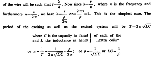
The chief dement determining the length of the wire is the distributed capacity and I shall presently suppose, that by proper design it is so reduced, that the length of wire is very nearly equal to the theoretical length, or the length of one quarter of the wave as computed from the velocity of light In this case then, if l be the length of wire in the "extra coil", and X this wave length, the length
This condition, as is well known, must be fulfilled, whatever be the length of the wire, to enable the maximum rise of pressure to take place, and also, p must be the same number for both systems, obviously. Now evidently in designing the apparatus, in any case, the experimenter will know approximately what e.m.f. he would wish to secure, and consequently he will have an idea how much difference of pressure he will have between the turns, and this will give him again an idea how he must place the windings most advantageously. He will furthermore recognize at once that the simplest form of such a coil, and also the cheapest will be one with one single layer and, settling upon this form, he will get an approximate estimate as to the diameter of the coil to be adopted.
This will, of course, depend much on the kind of wire he uses and particularly on the insulation, since the better the insulation the closer will be two points of the coil between which there will exist a certain maximum pressure. Granted now the diameter of the coil to be constructed is settled upon, it will be at once seen that, assuming turns are wound on until resonance is obtained, the inductance of the coil and the capacity of the same will vary in the like manner.
If more turns are wound on the drum their number will be proportionate to the length of the coil, therefore to the length of the wire, and the inductance will be proportionate — on the one hand, to the square of the turns or respectively to die square of the length of the wire, and on the other hand, it will be inversely proportionate to the length of the coil. Inasmuch as this length is likewise proportionate to the length of the wire, the inductance, on the whole, will be proportionate to the ratio p/l or to I, that is to say, the inductance of the coil, as more turns are wound on, will grow as the length of the wire.
And so will also, and obviously, the distributed capacity. And furthermore, and for the same reasons, under the conditions considered, both the capacity and the inductance of the coil will vary inversely as the distance of the turns which I shall designate τ. This is dear since, as far as the inductance of the coil is concerned, the number of turns will be inversely as τ, and the length of the coil directly as τ, hence the inductance will be inversely as τ; and, as regards the distributed capacity, it will be, of course, inversely proportionate to τ. Hence we can express both the unknown quantities L and Cr (distributed capacity) in terms of / and τ.
But it should be remembered that in the equation
A practical way is, to adopt a construction before suggested, securing a negligible internal capacity consisting of the placing of condensers in series with the turns of the coil and then, merely calculating one of the constants, assuming first a value for the other constant, whichever is the more convenient of the two. I have also found it practicable in some cases to avail myself of some methods of tuning allowing exact observations as to the rise of -pressure in the excited circuit, and to tune a small number of turns first to a much higher "Harmonic and, after completing this adjustment, to calculate the dimensions of the coil for the fundamental vibrations from the experimental data secured.
But in most cases such resources are not readily
available and an approximate idea must be gained in other ways.
There are a number of different considerations which, when followed
out in connection with the preceding, will lead to the establishment
of simple relations between the quantities primarily adopted and
will enable an experimenter to construct such a coil to suit source,
without previous experiment and some of these I propose to consider
on other occasions. Presently I shall indicate a way which, in some
cases to which the calculated data were applied, has given
satisfactory results.
Finally the
quantity C1 is inversely proportionate to the distance of the turns
τ. As to the dielectric constant it is only then important to
consider when the turns are quite close together so that the entire
space between the turns is filled with the dielectric. When the
turns are far apart this constant may be taken=l. From this it
follows that the capacity C
Since in the preceding the diameter of the drum is assumed, from practical considerations it will be convenient to find the number of turns N. The quantities D and T are, of course, interconnected since by assuming D and deciding on the pressure to be obtained beforehand, x is practically given. The diameter of the wire will in most cases also be selected beforehand so that then merely N is to be determined to satisfy the condition of resonance for any frequency specified. Now l=πDN hence substituting this we have from above:
This formula may serve to give an approximate idea of how many turns are to be wound on in cases when the length of the wire, owing to the capacity in the excited circuit, X / X is smaller then λ/4 (or respectively smaller than λ/2 if the circuit is not one of the kind illustrated in diagrams above — that is, one in which the potential on one terminal is many times higher than on the other, but an ordinary circuit, in which there is a symmetrical rise and fall of pressure at both the terminals), but the equation assumes that K, the dielectric constant, is= 1 or nearly so.
From a number of experiments the value for AT with wire No. 10 as used in preceding experiments was found to be nearly = 52/106. Introducing this value in equation for N and reducing the constant quantities we find
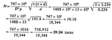
To see how close this formula will give the value of N in a special case take, for instance, the secondary with 40 turns experimented with before. In this particular case we have the following data: diameter of coil, average, 40 feet=480" =1220 cm. approx.
Resonance in secondary from previous tests took place with the
primary period being
This comes indeed very close, the turns being actually
40 for the condition of re
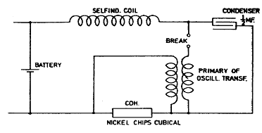
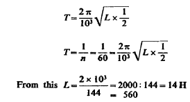
Here at each make and break we have a wave in the condenser, and tuning may be effected either by making n=60 or n—30. Best result seemingly, from former experiments with oscillators, seems to make n=the number of breaks. We have then,
Follow up.
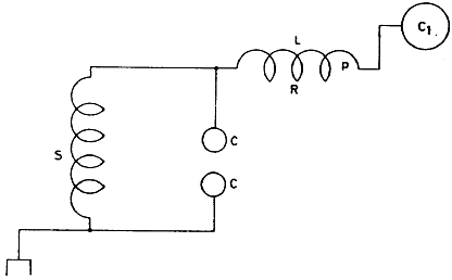
But using spark allows obtaining of great suddenness and using short wave lengths. The shortness of waves gives high e.m.f. and, therefore, great effect at distance. Without spark it is difficult to obtain high e.m.f. with short waves. Long waves on the other hand are less absorbed and allow exact tuning. Following plan seems to offer particular advantages that seemed to work well in New York oscillator.
S is the secondary of oscillator. To this is connected a coil L with capacity C,. The secondary is shunted by a condenser C C. This condenser can be of large spheres when practicable. No spark should go over the spheres C C and streamers should be prevented. Now the adjustment may be such that system L C1 is any upper harmonic. In this system Lp/R should be as large as possible. The free vibrations of L C1 can be transmitted upon earth through condenser C C.
Fig. 1) supply direct current 220 volt. Mercury break 1600 per
second. The secondary S1 with small condenser C and spark gap d,
primary P 2—3 turns.
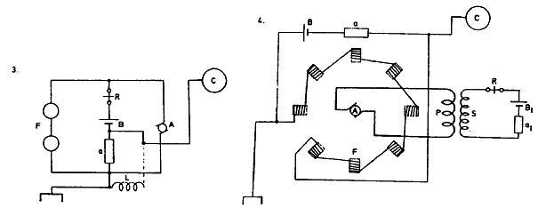
In case 1. sensitive device a with battery around field F. In armature circuit independently a receiver R and battery Bx. The receiver may be a relay, and in addition, to insure greater sensitiveness another sensitive device as a, may be joined in convenient manner in the armature circuit. In case 2. the armature and field circuits are joined in series and battery and receiver are in shunt to both, also sensitive device a.
In both cases the sensitive device may be also in series with the field or field and armature though arrangements 1 and 2 seem preferable. In arrangement 3. a shunt dynamo is shown, the sensitive circuit being also in shunt to the terminals of the dynamo. In addition, to regulate excitation of dynamo a shunt of high self-ind. is placed around the sensitive device a. Such a shunt may also be used with good effect in Fig. 2.
Fig. 4 illustrates one of the dispositions with an alternate and —
preferably — high frequency dynamo. The letters are
self-explanatory. The sensitive device a, may be omitted.
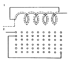
This is best done by following plan illustrated in Fig. 1 in
which there exists between each two turns one half of the total
difference of pressure which is active on the terminals of the coil.
But other arrangements may be followed as, for instance, illustrated
in Fig. 2, or similar dispositions may be made so that there shall
be the greatest possible difference of pressure between the adjacent
layers. Or the capacity may be increased by a conducting coating
over the insulation of the wire, which coating may be connected
suitably so to secure the maximum storage of energy in the coil;
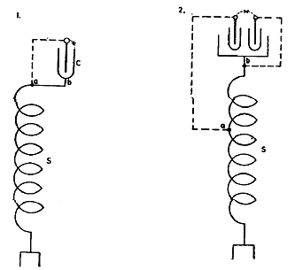
In Fig. 1. and 2. two of the many arrangements are shown. In Fig. 1. a condenser is placed at the free end of the secondary S of the oscillator, the other end being connected to earth. One coating is directly connected to the end of the secondary, that is to b, the other coating to a point a which has a suitable difference of potential with respect to b. By the operation of the oscillator energy is stored in the condenser C, which energy must all be supplied through the secondary, thus producing a large movement in and out of the earth.
A modified arrangement is shown in Diagram 2.
An arc may be maintained on the places marked x. Proper rules of
tuning are observed to secure best result.
Some arrangements of apparatus experimented with. Modifications of former plans.
Here relay is placed in series with sensitive device but in secondary. In this way slay is not affected by break. The charge of condenser may be regulated by varying L r by resistances in series with L or with S.
The relay is affected by the break in this disposition but the action was good in some instances; probably secondary S was more effective in breaking through the sensitive device a.
This disposition is simple and secures good results but one
disadvantage has been found in the short circuit of the secondary
through the condenser, which is necessarily too large for the high
tension secondary since it fits the primary P. The above defect is
reduced largely by the introduction of regulable self-induction L,
or similarly a resistance is used instead of L. In all these
dispositions of apparatus the effect upon the sensitive device is
rendered accumulative.
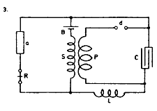
In this scheme the excitation of the condenser and therefore also of the sensitive device a was regulated by an adjustable self-induction and additional battery Bv The battery B can be in the same or opposite direction working through the device a. The former was apparently preferable.
Of these two connections the first was advantageous as the battery was not working except when the sensitive device was excited.
This was a plan (3) similar to one previously experimented with, only the battery B was placed so as to be able to charge the condenser.
To determine excitation of sensitive device to the point of breaking
down a self-induction coil L (very high) was placed around it (4).
This coil was also tried with connections changed as indicated by
dotted lines.
Some simple dispositions in the practical uses of apparatus as now available.
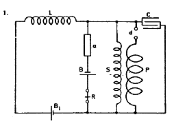
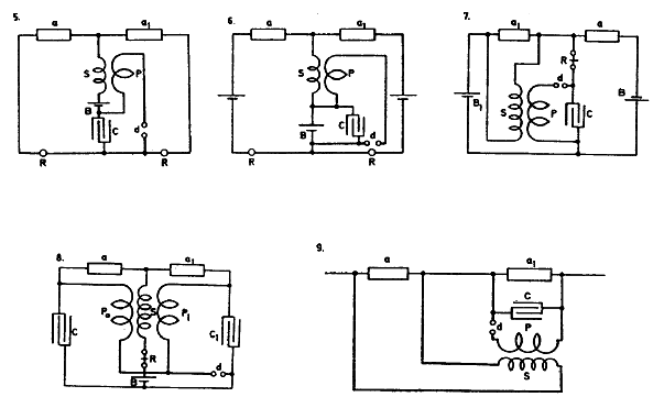
The connections in the oscillator as now manufactured are as shown in first sketch. In this way the apparatus is used as a sender. The connections are now by a throw of a switch changed in such a way that all can be used in receiving the message. One of the simplest connections is shown in the following sketch.
The relay R should have small self-induction. By battery B1 the excitation of device a is regulated. For facility of adjustment a resistance r is also inserted. The switch is to be worked out in detail.
In using the method of exciting the device a by means of oscillating
transformer the construction of a special apparatus may be obviated
by winding the primary directly upon the relay so that the relay
itself is the transformer. This is schematically indicated in the
sketches in which the letters indicate the same. In the first the
battery should be an open circuit, in the latter a closed circuit
type.
In both sketches 1) and 2) a relay R R is shown having one of its legs in one of the circuits and the other leg or coil in the second circuit. In this manner the impulses coming, for instance, from a distance as in telegraphy can be made to exercise an accumulative effect. The alternating impulses are led in through terminals 11.
Fig. 3. illustrates one of the connections of apparatus experimented
with with good success. The method of excitation and magnification
by means of an oscillating transformer is used and the relay and
secondary were connected either as shown in the plain lines or in
the modification indicated by the Botted lines. The letters have the
same meaning as in previous instances. In Diagram 4. similar
connections are shown, merely the self-induction coil L has been
done away with and secondary S adjusted accordingly.
Fig. 9. shows a plan followed in numerous variations and which is capable of excellent results.
Fig. 10. again shows a form of connections which works extremely
well. It is suitable for use in connection with single terminal
oscillators. The capacity or elevated terminal may be at C and also
at C\. Both cases result good.
The idea was to introduce greater regularity and reduce resistance of the path through the sensitive apparatus. Some arrangements worked well, for instance the one illustrated in sketch 2. In 3. both devices a and ax were shunted by a high self-induction L, the inductive and ohmic resistance of which was regulated so that devices a ax would break down at the slightest disturbance.
The results were fair but not better than before obtained with other dispositions. The relay was placed in a number of ways, best results when it was in the secondary S.
In Diagram 4. the same mode of connection was employed, only a battery and relay were placed in the bridge. The employment of the special battery Bt allowed some adjustments to be made not practicable in Diagram 3. Generally, battery Bl was differentially connected with respect to battery B.
Diagram 5. again shows a form of connections slightly modified, two
bateries being used in series to strain the sensitive devices aa\.
Results about the same. In Diagram 6. the connections were as
previously shown in Diagram 1. only the relay was placed in the
secondary S. This worked excellently. In. Fig. 7. the same
connections were retained only a high self-induction was connected
around the devices and regulated so that devices were rendered very
sensitive.
The employment of the mercury break particularly makes the apparatus
efficient, probably because of perfect regularity of working which
can not be secured by spring contacts or brushes. The efficiency is
also in a measure due to the small resistance of primary circuit
because of the large copper section and good mercury contact. It is
highly important that in preceding dispositions of apparatus the
break is of high frequency, the condenser large and best insulated
and the conversion in coil efficient.
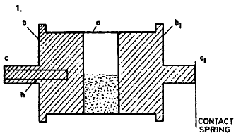
This device, and the manner of preparing it, it is now necessary to describe. In one form it comprised a glass tube 3/8" inside diameter, having two brass plugs fitted in its ends. The plugs had their inner surfaces highly polished and the distance between them was from 1/8"—1/2". The tube is illustrated in Diagram 1. in which a is the glass tube and b b\ the plugs of metal with narrow projections C C\ for support and contact, respectively.
The space between the plugs was filled about 1/3 full with coarse chips of nickel. These chips were made by a milling tool or punch so as to be as much as possible equal in size and shape, this being of considerable importance for the good performance of the instrument. The plug b had a small reamed (tapering) hole h in the center extending to some distance into the plug so as to enable its being placed on a small arbor fitting into the hole and rotated by clockwork at a uniform rate of speed.
In some cases when the working of the device was excellent the speed was 16 revolutions per minute. But often the instrument was rotated very much faster in which case it was merely necessary to increase the e.m.f. of the battery which was used to strain the device to the point of breaking down. A beautiful feature of this kind of device is that by regulating the speed its sensitiveness may be regulated at will and in this respect it is preferable to similar devices which are stationary, the contact after being established being broken by tapping.
The device acts exactly like a cell of
selenium, its resistance diminishing when the disturbances reach it,
being automatically increased in consequence of rotation and
separation of the chips when the disturbances cease to affect the
latter. The rotation of the device replaces here the property of
recovery which the selenium possesses, otherwise the similarity is
complete. To insure a quite satisfactory working and permanent state
I prepare this form of device in the following manner:
When the lower plug is brought to the required temperature, sealing wax is run around the rim projecting for this purpose, beyond the glass tube. The metal cylinder is now allowed to cool down slowly until the sealing wax is in some degree solidified when the instrument is turned over and placed with the other plug on the cylinder and the operation of sealing the joint between glass and plug repeated.
During this preparation the chips are of course at an elevated temperature and all moisture is expelled so that, when the instrument is ready, a thoroughly dry atmosphere exists within the same, this being essential for good performance. The atmosphere is, however, at a pressure slightly below that of the surrounding air. When the device is carefully prepared it works remarkably well, and in comparative tests showed itself superior to this kind of device of the form ordinarily advocated.
During a few days I carried on tests of this kind which brought out the good qualities of this kind of instrument. In one instance two of them were compared with a third device of the ordinary form in which the sensitive grains were immersed in an atmosphere considerably rarefied and contact was broken with a tapper.
In all three instruments the grains of nickel were of the same size and shape. One of the terminals of each of the devices was connected to a ground wire, while the other terminals were each joined to a piece of wire extending to a small height, these pieces of wire being the same in all particulars.
All the three devices were strained as far as was practicable by batteries so as to be at the point of breaking down and sensitive to a high degree. Although the pieces of wire extending into the air were only of a length of a few feet, all the instruments recorded the discharges of lightning up to about 30 miles as the storm moved away. At this point it was found necessary to set the instrument with the "tapper" so that it was still more sensitive when it responded but in an irregular manner, while the other two devices continued to record regularly up to a distance of about fifty miles when the disturbances ceased, probably owing to the cessation of the storm.
I inferred from these experiments, carried on for some time with the view of selecting and adopting the best form of such a device, that when the particles of metal are rotated they are, as it were, suspended in the air and in this condition more susceptible to the influence of the disturbances than when they are kept stationary. It seems, however, that when rotated, the particles are not so liable to stick together and cause irregularity of action such as observable in the ordinary form of such a device.
As to the amount of chips, if more are put in the instrument must be rotated at a higher speed or else the battery straining the dielectric must be weaker. Through this kind of instrument much stronger currents can be passed without damaging it and making it further unfit for work.
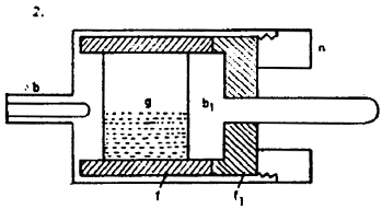
Another form of such instrument particularly suitable for experimentation is illustrated in Diagram 2. It consisted of a brass plug b with a fiber tube into which was fitted another brass or metal plug bi which was held in place by a fiber washer/j and metal nut n. In other devices of similar construction the space between the plugs was adjustable. This form of instrument was particularly suitable for testing the properties of sensitive grains g.
Before testing the grains and the
instrument as well were thoroughly dried. To get an idea of the
resistance of such devices when in either state, excited or not, the
resistance of many was measured under varying conditions. A fair
idea is conveyed by saying that, unexcited, they measured more than
1,000,000 ohms while the resistance would sink down to 300 or even
50 ohms or still less when excited. When highly sensitive they would
respond to sound waves at a considerable distance.
The spark gaps
were as long as obtainable in the box, that is, about 7 turns of the
screw on each side, possibly an inch or so. An approximate estimate
places the primary inductances at 75.000 cm. or Lp= 75/106
H. The primary capacity was 88 jars in each of the sets in series.
The capacity of one jar being approximately 0.0035 mfd.
The arc, horizontally passing about 32" long is very powerful, thick and giving a vivid light, the noise is deafening. The arc passes sometimes on a downward course. Is, it attraction or due to surgings of the air in consequence of violent explosions? When large balls 30" diam. are placed in the gap the spark length is nevertheless small. This shows the secondary can not supply the great amount of energy necessary for charging the large balls to full pressure.
This may be due simply to the imperfect inductive connection with the primary or to the small amount of power now available from the supply transformers, as there are only two of them, and the Westinghouse transformer works only at 1 /4 of the normal pressure. This would mean roughly 1 /16 of its total performance. On some points of the balls small streamers are observed; must be due to roughness or points on the places.
The balls will have to be gone over and all the surface polished up. It would be impossible for streamers to break out from balls of such size unless the pressure is a few millions of volts, which cannot be the case at present. A curious feature is to see the sparks deviate and follow wooden beams or planks placed nearby. I rather think this is merely due to an effect of the currents of air which are prevented from circulating freely on the side of the plank or beam.
The intensity of the vibration in the primary is evidenced by sparks passing between the turns of the regulating self-induction coil in the primary. Between the beginning and end of the coil, although only a few of the turns are inserted, the sparks are sometimes 3" long. This shows a very high e.m.f. on the primary and I almost think there must be a mistake as to the pitch estimated which, judging from these sparks, would seen to be much higher.
This is to be investigated closer. Experimentation shows that it is very decidedly better to adopt one turn of primary instead of two and if a lower frequency is desired rather to increase the primary capacity. With one turn the explosions are more violent and the regulation is much more convenient. In these experiments the jars do not seem to be much strained, which indicates well.
At times sparks will break through inside of the secondary between the turns and to the ground. The sparks are very strong from small wires attached to the free end of the secondary more so than from thick wires. When a coil was connected to the free secondary end the vibration could not be well established, evidently the coil was "out of tune" and by its capacity and inductance interfered with the free vibration of the secondary.
The sparks went from the gap-box to the ground though the box was well insulated; there is danger of inflaming the building by this or by the secondary sparks following the wooden structure. The experiments were continued with 7500 volts as yesterday but the working was unsatisfactory. This showed finally that yesterday one of the jars in one set was bad and there was only one set acting, the other set being short circuited; that is why an e.m.f. of 7500 volts was sufficient yesterday.
The Westinghouse transformer gains in e.m.f. as jars are put on, the maximum rise seems still remote, this argues well for the economy of the transformer. The incandescent lamps are all destroyed in consequence of the intense secondary vibration, the filaments being broken by electrostatic attraction towards the glass. Lamps were spoiled at a distance of 40 feet from the secondary free terminal! This action is likely to give trouble in future experiments. A curious observation is that all horses shy.
It is due to sound or possibly to current action through the ground to which horses are highly sensitive either owing to greater susceptibility of the nerves or perhaps only because of the iron shoe establishing good ground connection. I am not quite certain that the secondary vibration is fundamental although for a lower or higher tone it is too powerful. The external gaps used in some trials seem to improve the action somewhat in rendering the discharges of the primary more sudden. If time should permit the vibration will be investigated by a rotating mirror to be prepared. |
 .
. 
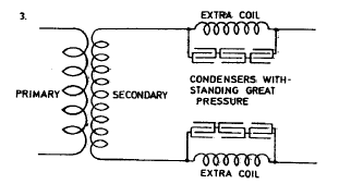
 , C is capacity associated with the coil on the free terminal
and not the distributed
capacity. In case, therefore, we should make the capacity on the
free terminal very large in comparison with the distributed capacity
of the coil, or if capacity be associated with the coil in other
ways, as by shunting the coil with a condenser as in sketch 3. — or
in any other way, but so that the distributed capacity may be
neglected, then the design of the coil is much simplified, for then
one of the constants, preferably C, can be adopted beforehand and
the other constant calculated. It will be in such case better to
adopt first a capacity, because it is easy to get an idea of what
kind of condenser to use when the pressure of the terminals of the
coil is approximately known.
 is
always a function
of the distributed capacity C, and furthermore a linear function, so
that C=K1C1, where K1 is a constant, the value of which is to be
deducted from the results of many varied experiments carried on to
this end. But this capacity C1 is, as has been found in many
experiments with coils of widely different dimensions, directly
proportionate to the length of wire and to the diameter of the same
and furthermore to the diameter of the drum. The latter will be
understood when it is considered that the greater the diameter of
the drum the greater is the potential difference between the turns
and, consequently, the greater is the amount of the energy stored in
the coil with a given length and diameter of the wire.
  when
when 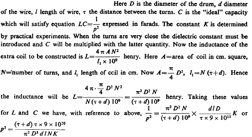


 , this was also the secondary period and from this n=20,700
approximately and this gives p= 130,000 very nearly. On the basis of these data
we would have: